This is part 4 in a series of posts in which I will document my journey (and mistakes) of building a 6502 based computer.
A Whole System
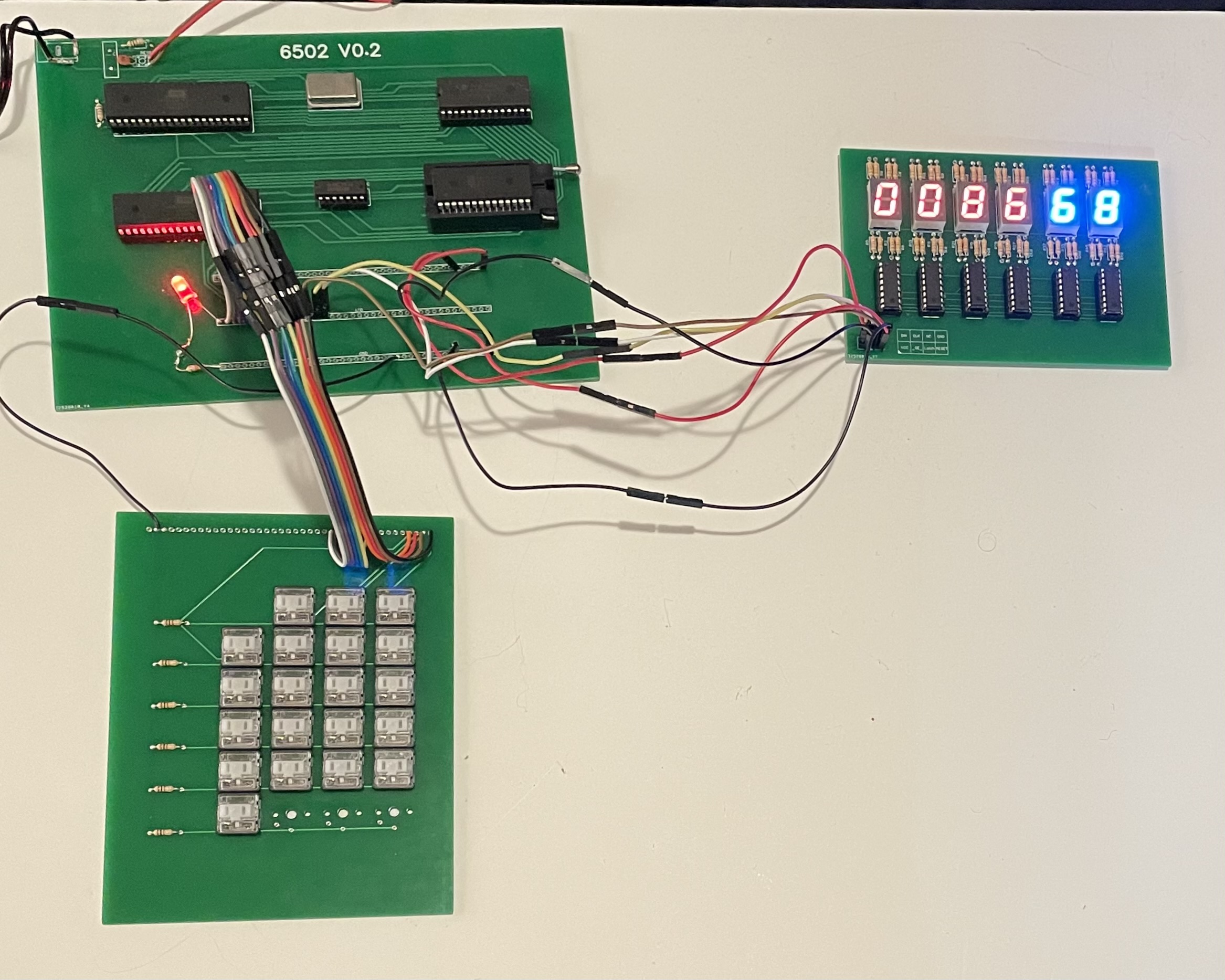
I now have a compute board, screen, and keypad. Linking it all up is just a case of running wires from each board back to the I/O point on the compute board.
Software
My next challange is to write some code to make it all work.
Screen Update
The screen is just a shift register system and so it can be driven much like an SPI bus, so I created a “SPI_Write_Byte” function.
SPI_Write_Byte:    ; writes the byte in A register to SPI bus.
  sta ZP_Temp ; zero page
  ldx #$08
SPI_loop:
  asl ZP_Temp ; bit shift zero page
  bcc SPI_out_low_bit
  lda PORTB
  and #0b11111100 ; data low & clock low
  ora #0b00000010 ; data high & clock unchanged
  sta PORTB
  inc PORTB ; set clock high
  dec PORTB ; set clock low
  jmp SPI_bit_done
SPI_out_low_bit:
  lda PORTB
  and #0b11111100 ; data low & clock low
  sta PORTB
  inc PORTB ; set clock high
  dec PORTB ; set clock low
SPI_bit_done
  dex
  bne SPI_loop
  rts
The screen can display three bytes as hex, which is six digits of a seven segment display. Each byte to be displayed gets split into two 4 bit sections, those 4 bits are an index to an array to the right bits needed to display the single hex digit. In this example $400 is the byte to display, $420 and $421 are bit masks to turn off single bits of the display. The bit mask magic allows for turning on or off the decimal point or blinking the whole digit.
  lda $400
  tay
  and #$0F
  tax
  lda Array_7seg,x
  and $420
  jsr SPI_Write_Byte
  tya
  and #$F0
  lsr
  lsr
  lsr
  lsr
  tax
  lda Array_7seg,x
  and $421
  jsr SPI_Write_Byte
Keypad Read
The keypad is driven as just a row and column system, we set each row high one at a time and see if any column is high, then we do (col*4)+row math to get an index to an array for what keycode to return. $405 is just a temporary storage location that could be moved to ZeroPage.
readKeypad:
  ldx #$04 ; Row 4 - counting down
  ldy #0b10000000 ; Row 1
ScanRow:
  sty PORTB
  lda PORTA
  and #0b00011111 ; mask off keypad only
  cmp #$00
  bne Row_Found
  dex ; count row down
  tya
  lsr
  tay
  cmp #0b00001000
  bne ScanRow
  lda #$ff
  rts
Row_Found:
  stx $405 ; store row
  ldy #$ff
FindCol:
  iny
  lsr
  bcc FindCol
  tya
  asl
  asl  ; col * 4
  clc
  adc $405 ; add row
  tax
  lda KeypadArray,x
  rts
The keypad has 16 buttons for the hex digits, and also 4 control buttons of “R”, “W”, “X”, “ENT”.
Memory Monitor
The memory monitor is a simple state machine and pushing R, W, or X moves between modes and allows for Reading, Writing, or eXecuting from memory.
This allows the user to “toggle” code into memory and then run that code.
The code for the monitor is not ready to share and a bit large for a blog post.
What’s next?
In part 5 we will create a single PCB with compute, keypad, screen and an SD card interface.