This is part 1 in a series of posts in which I will document my journey (and mistakes) of building a 6502 based computer.
Why?
It could be said that this is not a vaild question, this is about learning and creating things and so questions like “why?” don’t make sense.
For many years I have been interested in building a simple 6502 based computer, something in the range of a KIM-1
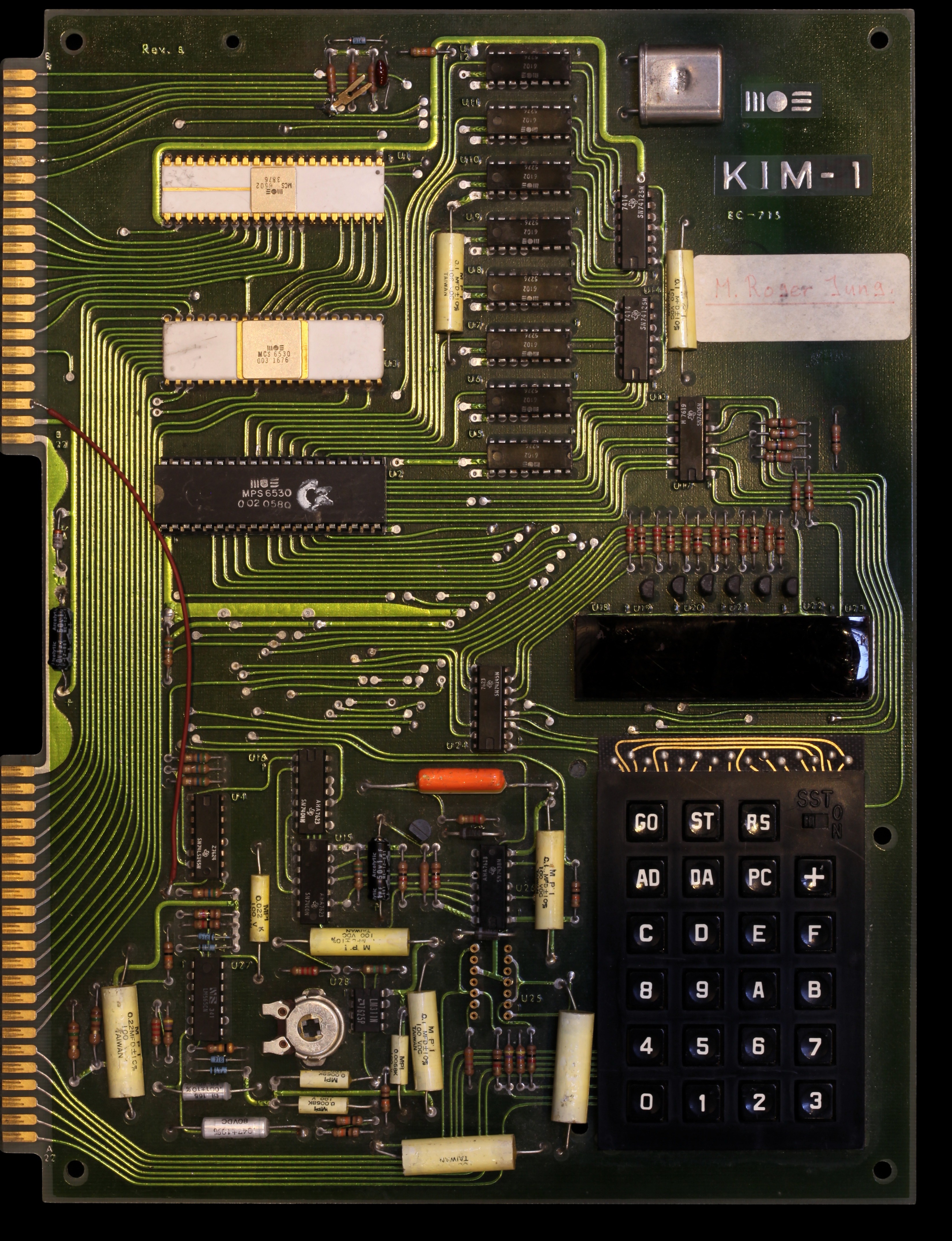
In the last year I have been watching the Ben Eater Youtube channel in which he makes a simple 6502 system on a breadboard and this has given me a nice starting point.
Why the 6502?
The 6502 was the CPU used in many of the computers of the 1980s including the Commodore 64, Apple II, and Atari 2600. The MOS 6502 was very popular due to its low cost. When it came to market in 1975 it cost only $25 (equivalent to $120 in 2021) compared to the Motorola 6800 at $175 (equivalent to $840 in 2021).
The modern version of the 6502 is the WDC 65C02
6502 specifications
- 64K of address space.
- Memory mapped I/O.
- A clock speed of 1 or 2 MHz. (modern versions can run at 14MHz)
Wikipedia has a page of full history and specifications of the 6502
The basic design of a 6502 system.
Depending on your design you can have a working computer with 5 chips.
- 65c02 as the CPU.
- 65c22 for I/O
- AT28C256 EEPROM
- AS6C62256 32k SRAM
- 74HC00 for address decode logic.
Ben Eater has a design that is my starting point, but I am not using his LCD screen.
How hard can it be?
I am not a fan of breadboard electronics, too many wires that can get bumped.
So I decided to jump stright to a PCB, EasyEDA makes this look easy.
Board #1
The first board I designed took 8 days to arrive.
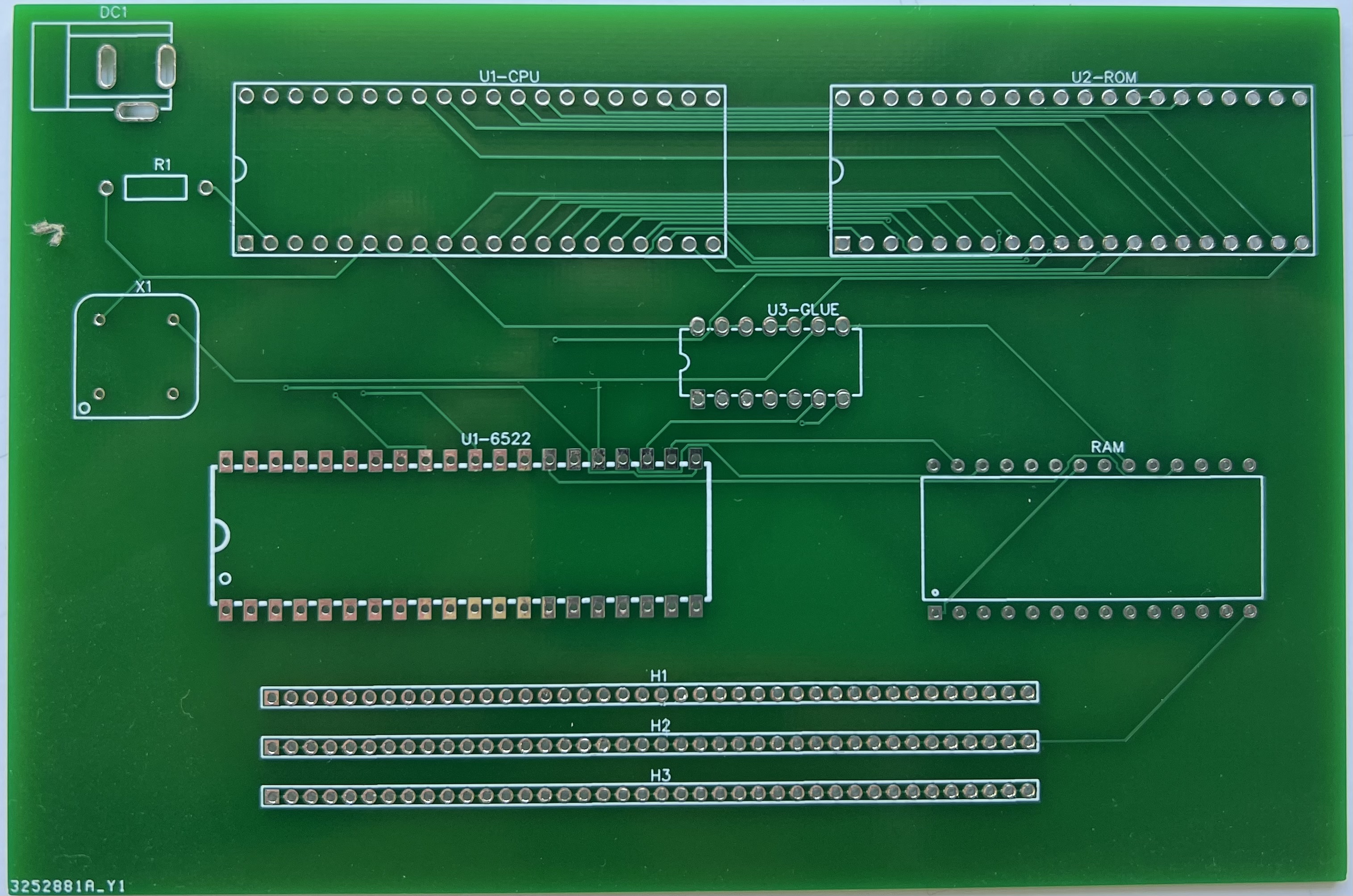
But the tracks seemed too small and so I did another design with wider tracks and I spaced the parts out a bit to give me more space to fix things.
Board #2
The second board I designed took another 8 days to arrive.
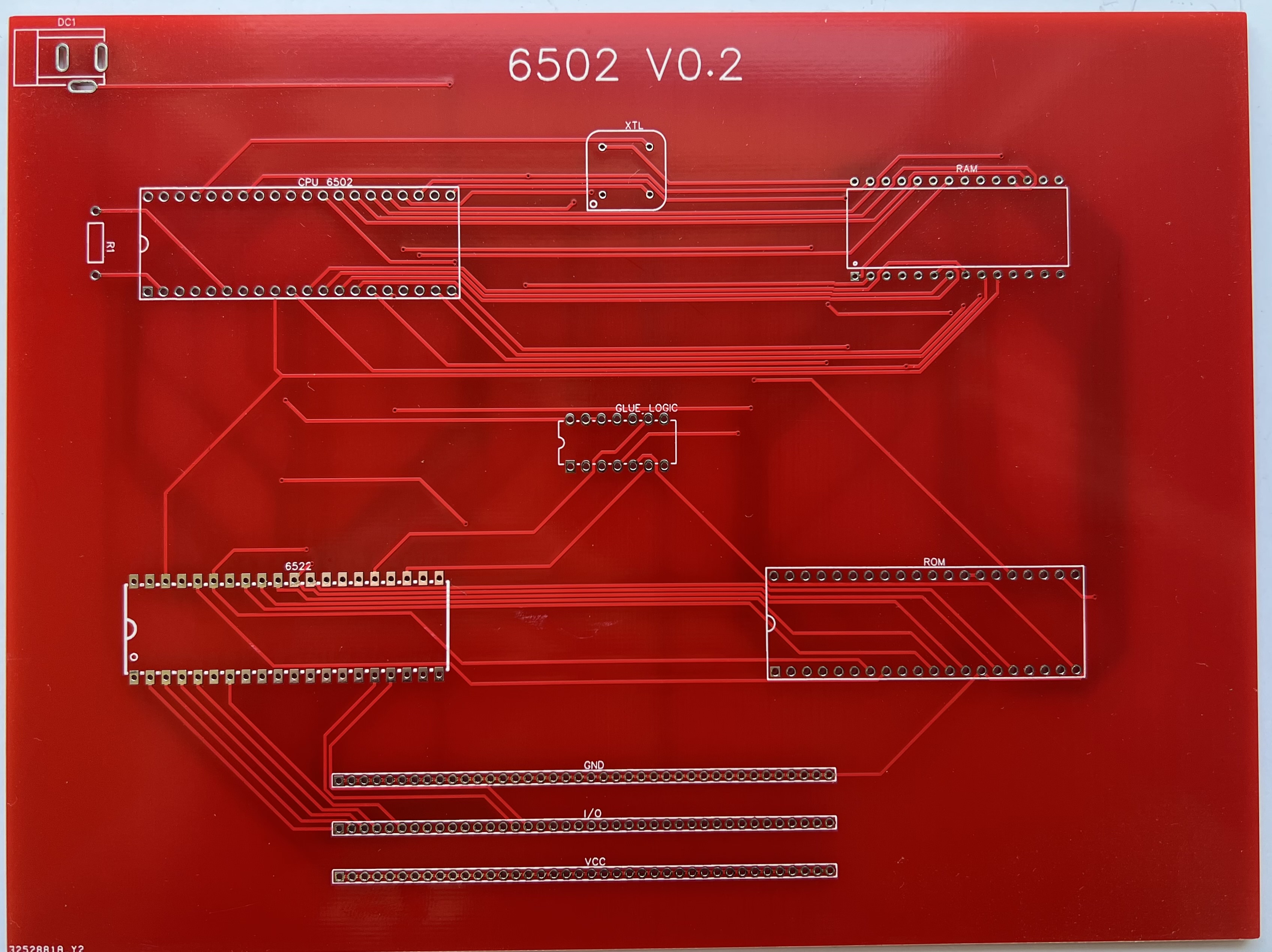
When I got to checking the parts I found the ROM footprint was all wrong. In EasyEDA you can have a symbol in the schematic and a footprint on the board layout that don’t match.
Board #3
The third board I designed arrived in about 10 days.
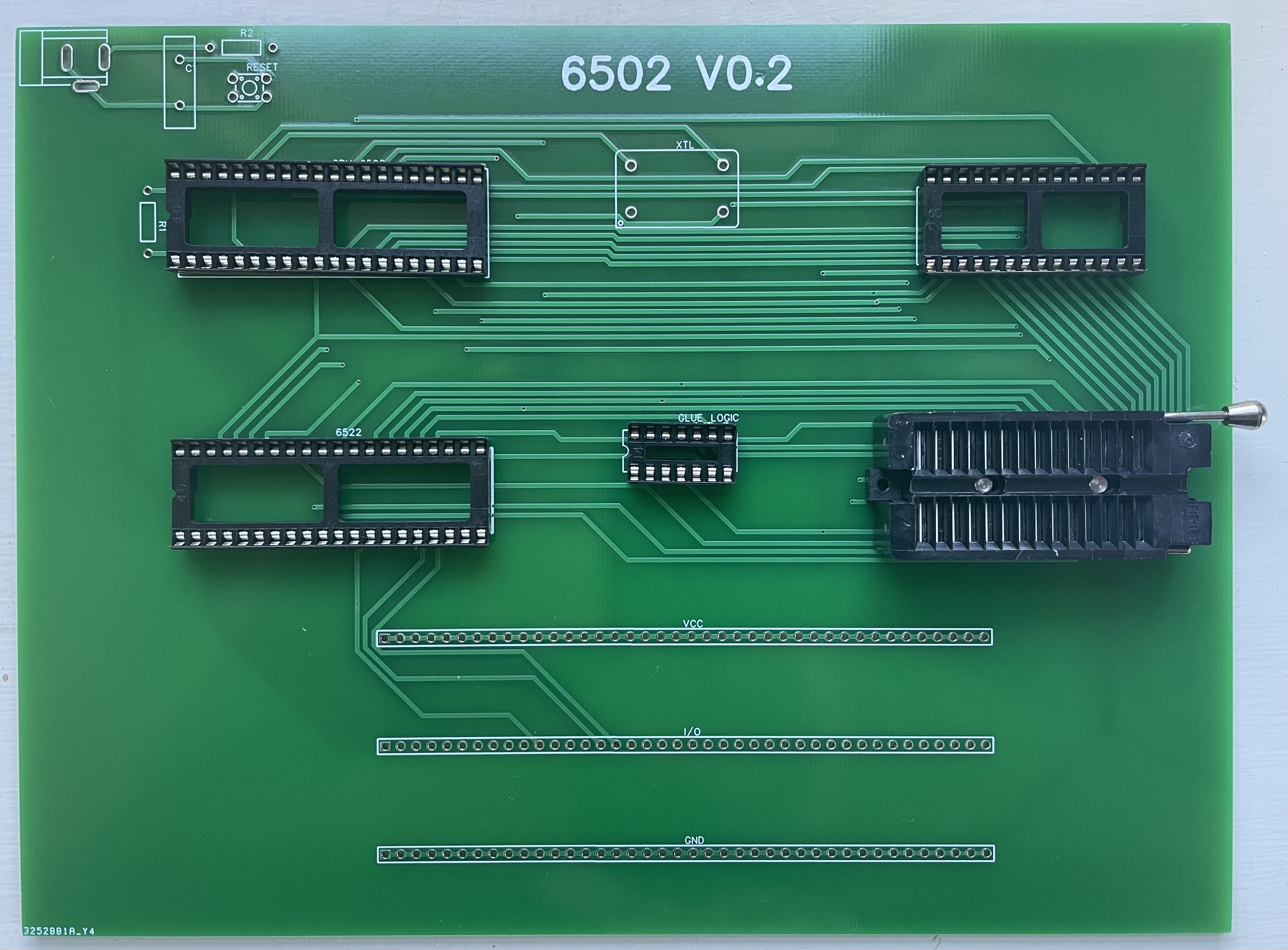
It looks good, so I soldered it all up.
It turns out that VSS is not the same as VCC and so I got the power lines for the 65c22 backwards.
But that can be fixed with some bodge wires.
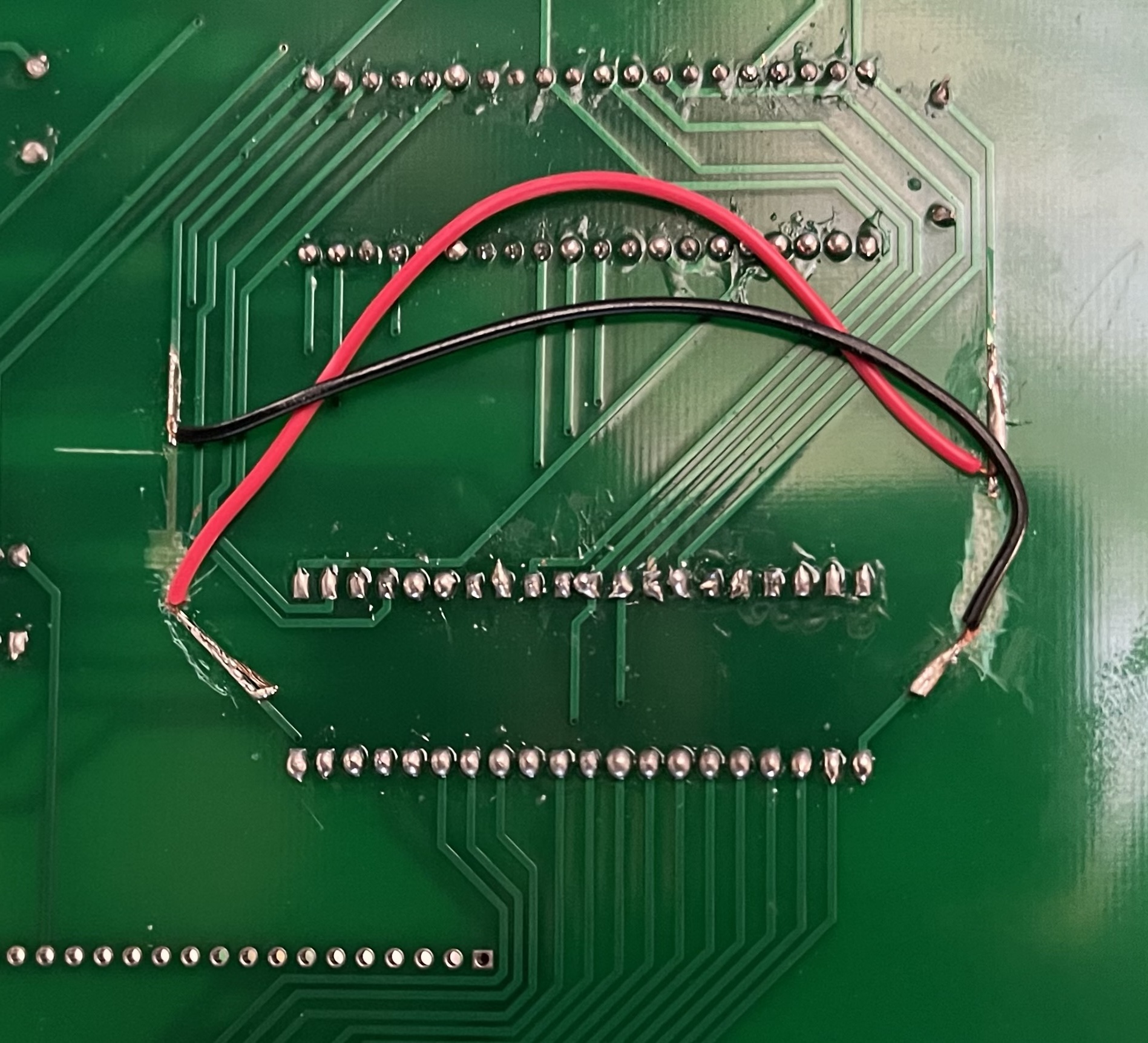
At this point I have a simple blinking light.
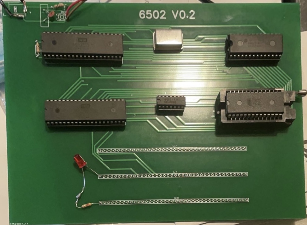
Note the choice of sockets for all the chips, this is because I don’t trust my soldering skills. Also I decided to use of a ZIF socket for the EEPROM as it will be swapped in and out often.
What’s next?
In Part 2 I will cover the input and output.